
After reading a Radcom article about a 10MHz locked ADF4351 Arduino controlled signal generator thanks to Alain Fort F1CJN described here, it seemed the perfect module for testing equipment locally as I didn’t have anything like this.
Once the pieces arrived from China it worked perfectly with a 10MHz GPSDO input using the instructions from Alain’s page above and the black ADF4351 board after disconnecting the on-board 25MHz clock.

When connected, the above worked fine and did okay on the desktop it wasn’t suitable for moving about or with the jumper cables for long term storage/use. A box was ordered large enough to place all of the bits in and to allow SMA & DC inputs as well as another shield that didn’t have the headers I’d put on the above one.
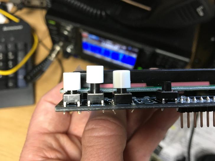
The Arduino LCD/Button shield works well but doesn’t lend itself at all well to being installed in a box. The LCD brightness adjustment trimmer is too big, there are some header pins sticking up to the LCD level and the buttons are too far recessed for access through a box. Some discussion on the ukmicrowaves mailing list gave pointers for getting around these problems.
Firstly the buttons were all removed and the trimmer was moved to the other side of the PCB.
 I wasn’t sure of the size of buttons to replace the originals with to allow them to be pressed when mounted in the case so I had also ordered a mixed pack on eBay to allow picking the appropriate size. I also ordered some white caps for the tops which would eventually be glued on. I eventually settled on the combination lush with the LCD.
Now came the part I wasn’t looking forward to, drilling and cutting the case. The LCD shape along with the four mounting holes was drawn out based on measurements from the board and cut. I don’t have any nice tools for the LCD rectangle cut so cut two sides with with a hand hobby saw and others with a rotary tool to compare the finish as wasn’t sure of the best approach. The rotary tool was fast but gave a terrible finish, the hobby saw plus sanding gave by far the better result.
The more tricky bit was the button measurements and I couldn’t find a PCB diagram for the board. Putting some fabric tape on the inside of the case and ink on the top of some temporary placed buttons I pushed the LCD in to it’s fitting which after a couple of goes left an imprint on the inside.

This allowed me to drill an initial hole from the inside before turning over to drill an appropriate sized hole from the other side.

Once I had validated the holes were lined up, they were expanded to fit the white caps using a drill and a deburring tool. I then checked the button lengths for the best match, soldered the buttons to the board and glued the white button caps to them.
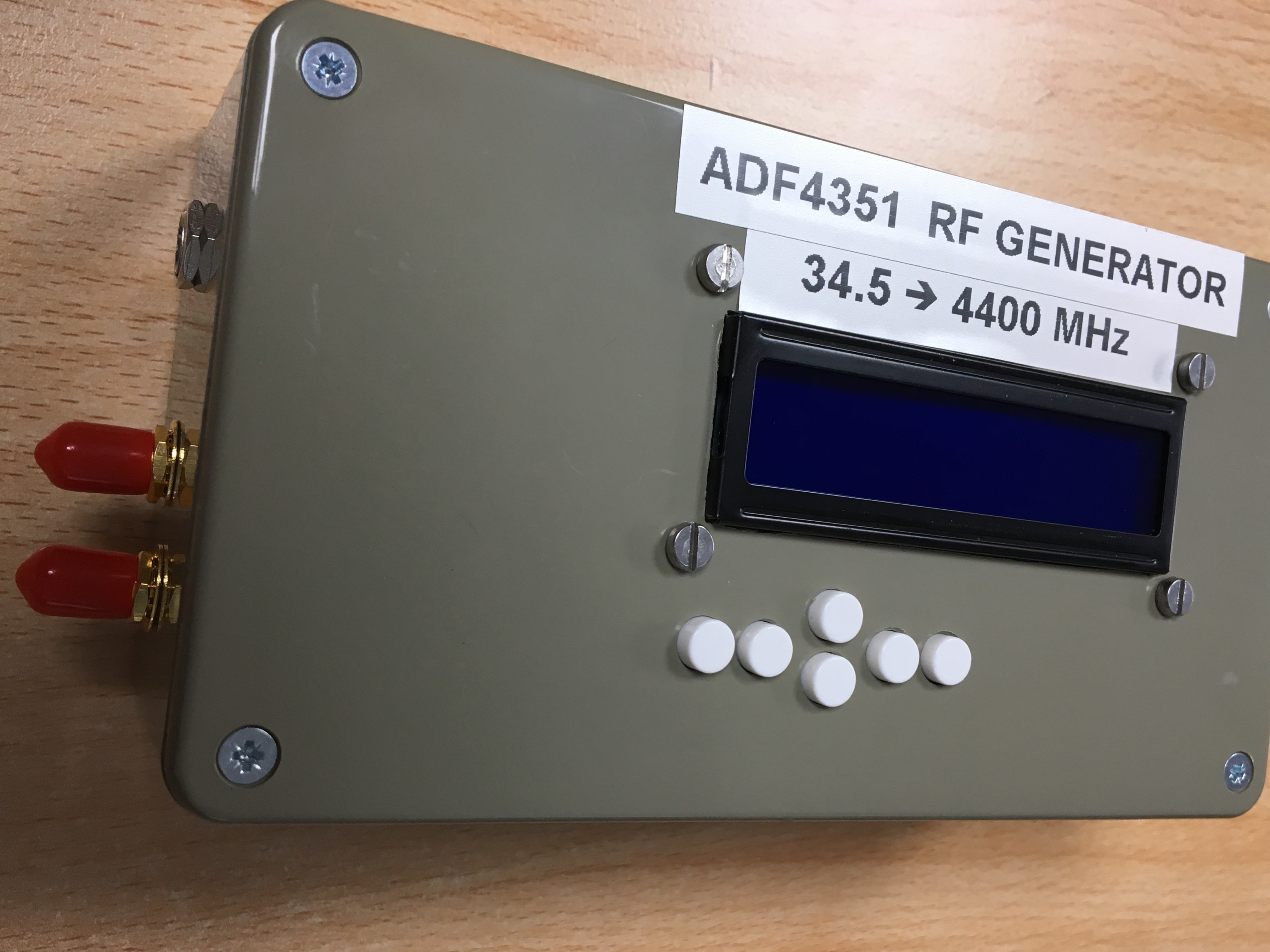
Three holes were drilled in the side for two SMA and a DC input and some stickers added to make it look better by hiding the messy top cut made by my bad effort with the rotary tool…
The inside has the LCD shield and Arduino attached to the lid using machine screws and some spacers to hold things in place. The Arduino needed it’s DC socket removed to fit flush with the LCD shield. Wires were soldered directly in to the Arduino for the output to the resistor divider and DC input.

In the picture above the DC input is going to the Arduino DC input. However the regulator in the cheap Arduino Uno copy I’d obtained from eBay turned out not to work with a 12v input in the same way as the genuine Uno I tested with had. To sort this I skipped the regulator by putting a small buck converter in the case to let it regulate the voltage to 5v and connected it directly to the 5v on the Arduino. As well as solving the problem, the converter gives better a 6-20v input range potentially at the expense of the converter introducing noise.
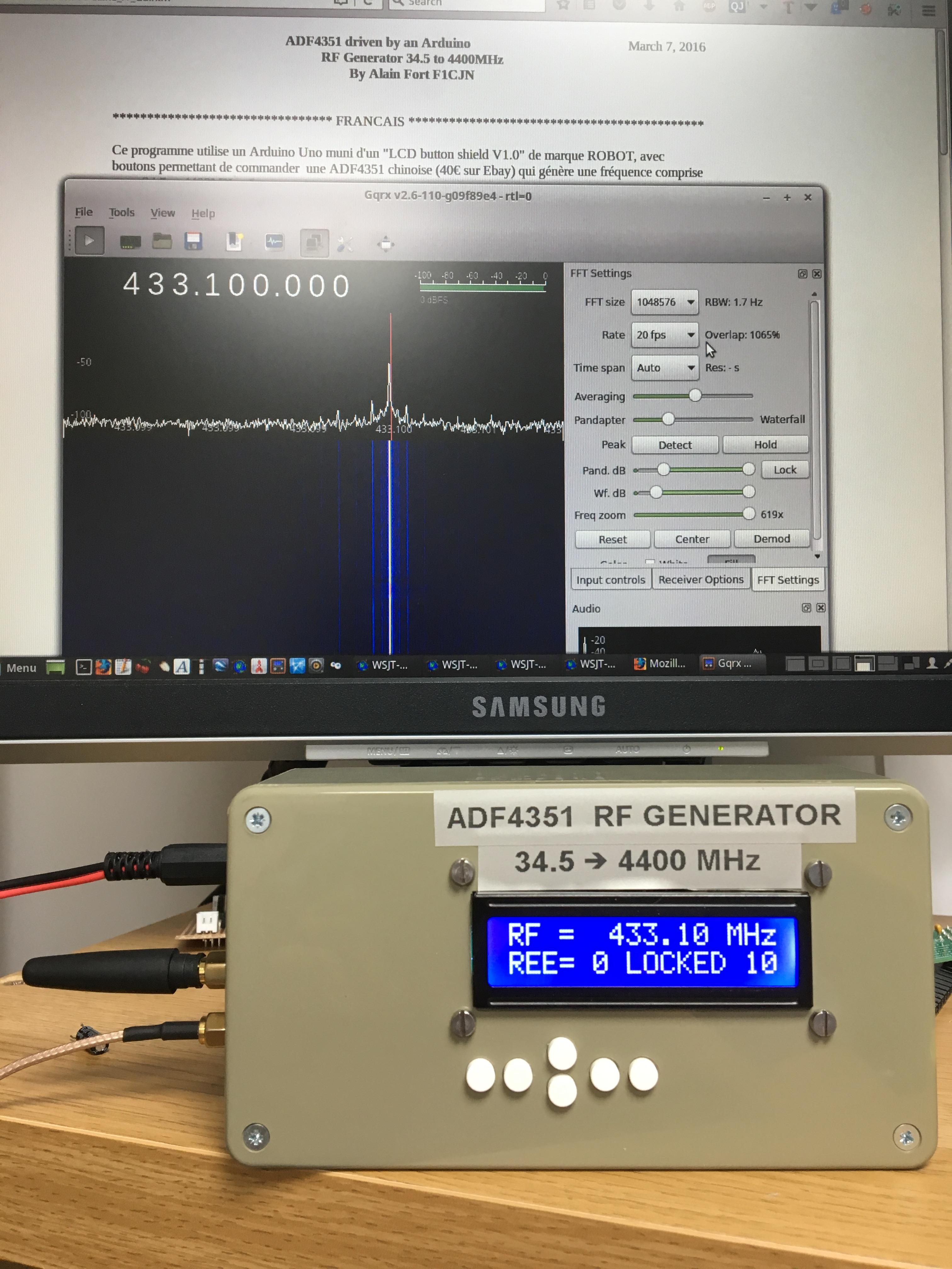
The harmonics produced are strong enough to provide an accurate marker at 10GHz and likely beyond.

Hello.
I recommend to use the tool called Dremel 3000 for tasks like this. The best thing about Dremel (comparing to cheaper alternatives) is that is has lots of “extensions”. E.g. I use the one that turns it into a drilling machine, model Dremel 220-01. Its irreplaceable if, for instance, you are making a home-brewed PCB and have to drill like 200 holes in it.
If you decide to buy a 3D printer, RepRap Prusa i3 is OK. However be prepared that printing even a relatively simple model takes a few hours. Also I recommend to use PLA filament, not ABS. ABS is very cranky, it requires a very specific temperature on all layers of your model, so you have to build a thermal camera which may not work, etc… With PLA you just press a button and get the result.
LikeLike
Hi Aleksander,
Thanks for that tip, my (cheap non-Dremel) multi tool is due for replacement after years of use and something that can be mounted and used like a drill press in that way would be useful. I was using a rotary cutting disk for the bad cut but by hand which wasn’t ideal, fast, but also fast to make a slight mistake worse.
A 3D printer is on the want list! I’ve ordered a couple of printed parts with designs on Thingiverse from others recently. So until I need to print a lot of things or custom things I can get away with having others do the printing for me, maybe later this year might treat myself 🙂
LikeLike
Searching ebay for those buttons, can you help I wonder with a URL?
Are there different colours?
Thanks Nick
LikeLike
Hi Nick,
Can’t remember where exactly I got them from, might have been along with some switches but searching for push button caps should work.
Found some on Aliexpress and ebay, check to make sure they are correct though 🙂
https://www.aliexpress.com/item/50pcs-lot-7-Color-Plastic-Cap-Hat-G62-for-6-6mm-Tactile-Push-Button-Switch-Lid/32818007745.html
https://www.ebay.co.uk/itm/6mm-WITH-CAPS-PCB-Mounting-Momentary-Tactile-Push-Button-Switches-SPST/232345524357
LikeLike
1. That sure looks like a variable resistor, not a variable capacitor.
2. Using a switching power supply (buck converter) is going to introduce lots of noise at the switcher frequency.
3. Have you looked at the output of this thing on a spectrum analyzer? I assume there is no output filtering so how high are the harmonics relative to the fundamental?
LikeLike
1. It sure is, changed thanks!
2. Yes quite likely, hadn’t planned on using the buck converter it was just to hand, shouldn’t even be needed with a proper Uno that doesn’t have a crappy regulator.
3. No filters and the strong harmonics are the main reason I put this together to have a reasonably accurate stable 10GHz marker for testing purposes which the third harmonic provides. I’ve not compared the levels of any to the fundamental no. I understand the harmonics are still useful at 24GHz but don’t have anything for measuring that high.
LikeLike