Christmas With RfCat

Having lost the RF remote controlling the power to the Christmas tree lights a couple of times I thought it would be a good time to try RfCat with the YARD stick one that has been sitting neglected since I bought it a while back. Nothing here that hasn’t been written up 101 times by others!

The RF controller has multiple buttons for switching the different mains switches on and off individually or all on/off at the same time. As these are only button presses I’ve just aimed to replay the transmissions not really caring about the content.

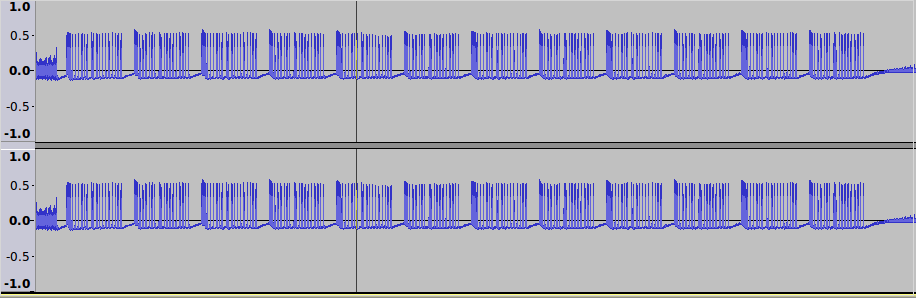
The signals are on off keyed and repeated when holding the button, looking at these in audacity was pretty much as described in earlier posts here and here. It’s been a while since I’ve done this sort of thing so was a decent refresher project.

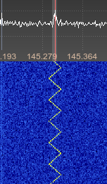
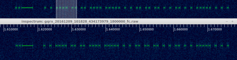
Additionally this time around I’ve used inspectrum with the IQ output from GQRX which along with its cursor option makes getting the timings correct a lot easier.

screenshot-inspectrum-gqrx_20161209_103307_434173979_1800000_fc-raw

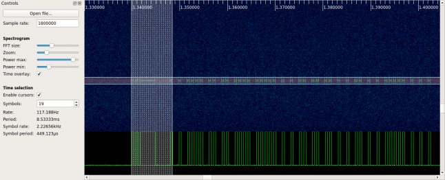
Inspectrum with cursors enabled

Using the stats.py script as described in earlier posts with a wav file to make a guess gave the following output (not from the same button as in the screenshot):

./stats.py -i ../allon.wav -c 1 -t 30
 The whole lot: 000000010101111110000001001001010101001010001010010101010010101010100100100101001010010100100100101001000100101001010100101001

After removing the initial zeros this matched up nearly perfectly with the inspectrum/audacity output. I added an additional 1 and 0 to the long on/off periods at the start to have it match better.

Now I needed to send this out using the RfCat with the above input. This was surprisingly easy to get working in Python with RfCat and worked the first time after following some online examples.

Firstly I needed to convert the stream to use with RfCat which gave:

\xaf\xe0\x22\x2a\x8a\x28\xaa\x2a\xa2\x22\x8a\x28\x88\xa2\x22\xaa\x22\x20

Then to send this in RfCat:

d.setMdmModulation(MOD_ASK_OOK)
d.setFreq(434400000)
d.setMaxPower()
d.setMdmSyncMode(0)
d.setMdmDRate((int)(1.0/0.000450))
d.RFxmit("\xaf\xe0\x22\x2a\x8a\x28\xaa\x2a\xa2\x22\x8a\x28\x88\xa2\x22\xaa\x22\x20")

The timing was taken from the inspectrum symbol period as pictured above, modulation and frequency self explanatory.

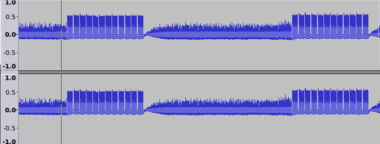
Comparing the original signal to the one sent by rfcat they are pretty much the same and the switches accept the signals as intended.

screenshot-59

Original signal top, RfCat bottom

I wrapped this all up in a small python script containing all the on/off values and am now using it to turn the lights on and off with a cron job for the month.

Another way to receive the data and skip the iq/wav analysis full stop is just to use RfCat to receive the signal.

I did try this first and didn’t get too far before trying the above instead but it was easier after having done all of the above and having the timings correct and after reading a great post here which is a good guide to this sort of thing: http://andrewmohawk.com/2015/08/31/hacking-fixed-key-remotes-with-only-rfcat/

With the same RfCat settings as above we run d.RFlisten() and get the following:

screenshot-60

RfCat button press output

There’s some obvious repeated data in the screen shot. Taking a few of the repeats out and converting to binary we end up with a string that matches the output from stats.py but for a slightly longer preamble but this doesn’t make a difference to the outcome when we retransmit the above, the switch switches as expected.

It is a lot quicker and less fiddly to just do all of the above with RfCat entirely but had I not worked through it from the method I knew already I’d have struggled to get it working as quickly. Next time with a little better understanding hopefully it will be easier.

Advertisement

Analysing An Active RFID Card

The next device from the box of bits was a pair of active RFID cards from a top of the range vehicle security system used around 2001-2003. These tags were required to be on your person to start the car in addition to a key. This is just an analysis of the cards RF transmissions and not the system itself as I don’t own one.

Popping open the two cards we can see they have similar layouts but the newer board on the right doesn’t look as clean and does not have any PCB labelling. The keys each have a serial number sticker on the back of the PCB as well as having it printed on the front of the card.

The two RFID tokens.

The two RFID tokens

There are not many components on the card, we can see an SMD EEPROM along with a small SAW device and the PCB antenna. Looking up the SAW device documentation indicated that it will most likely be transmitting in the 433Mhz ISM band on 433.900.

The batteries in the cards had long run out, so we just hooked them up to an external power supply and monitored with the HackRF and GQRX, this would have worked fine with the RTL SDR device too. We see a short transmission on 433.920Mhz roughly every 5 seconds but it does vary a bit. The frequency reading is wrong below as the screen shot was captured off an IQ replay.

Clear signal.

Clear signal.

On looking at this a bit closer with baudline it unsurprisingly looks to be an on off keying AM signal. Importing a saved audio clip in to Audacity shows the signal, the first capture looked a bit odd with dips and other strangeness but it turned out I was a bit off frequency, fixing the frequency gave a clearer capture.

Unclean off frequency capture.

Unclean off frequency capture.

The first thing I wanted to do was level off the signals to allow for an easier visual comparison, the capture below shows the original signal up top and the altered one below. I used a the same script I used with the previous doorbell project and we can count 78 peaks in each tokens transmission.

Full capture with the second channel prettified

Full capture with the second channel prettified

Comparing transmissions showed that the token is beaconing the same pattern over and over so maybe they are easily repayable as with the doorbell. Interestingly when we look at the two tokens with different serial numbers next to each other we can see a quite long period at the start where they roughly match followed by not too dissimilar patterns after. At this stage I’m guessing the serial numbers are likely just being beaconed following the preamble/synchronisation signal.

The signals patch prior to the red line.

The signals match prior to the red line.

The timings were not particularly consistent even in the initial preamble to allow them to be lined up easily and my previous script to guess binary output based on the period of time (NRZ) was not working perfectly due to this.

There appeared to be two spacing times, one around 18 samples and one around 45 samples but these varied by +/- 10 samples which added up to a large error by the end of the 78 state changes. In order to sort this out I added an option to the script we created for the doorbell to make the sample spacing gaps even. So in this instance a sample space of >30 = 40 and <30 = 20 gives us an easy to compare output.

A resized comparison showing some matching digits

A resized comparison showing matching digits

Now that the WAV file has evenly spaced samples, we can compare them easier as can be seen in the image above of the two tokens beside each other. The initial preamble matches perfectly between each transmission up to the previously indicated red line and would seem to have 5 8 bit components going by the peak count. Handily enough, the tokens 6 digit serial numbers share one digit in the same place and we can see where these match between the two tokens, we can also see this digit repeated again in two other places in the second serial number, these are indicated in the image above.

Now on to the actual decoding! The number of peaks, 78, doesn’t really tally with the indication from the preambles/synchronisation that each part is 8 bits. We now have to turn to a different encoding mechanism commonly used for this sort of cheap OOK device, Manchester encoding. This is better explained somewhere like http://www.quickbuilder.co.uk/qb/articles/, but the idea is that instead of counting the peaks and troughs as a high or low as you might when taking a look at it, we use the transition between high and low values in the middle of a set time period to define the 1 or 0.

As we have already altered our file to have a consistent spacing of 20 or 40 samples we can script reading this Manchester encoding easily by starting at the first state change position, measuring forward 39 samples and detecting whether the value increases or decreases in that time period and repeating this process until the end of the file.

This gives us the following binary output which looks very promising, we can see the matching patterns for the shared digits in the serial numbers between the tokens. The first 5 preamble bytes are the same, 6 is different, and 7 is the same matching the digit 0 in each of the tokens at position 2 with token 2 having two further digit 0’s all in bold.

Token 1: 11111111 01010101 10101010 01010101 00110110 00110001 00110000
Token 2: 11111111 01010101 10101010 01010101 00110110 00110100 00110000
Token 1: 00110001 00111001 00110011 00110010 00000000 10111011
Token 2: 00110000 00110111 00110000 00110011 00110000 11100100

Now converting each of these from binary to hexadecimal we get a match for ASCII characters so by adding an extra decode step to the script processing the file containing the resized signal, we can see the serial numbers they are broadcasting!

stats.py -i gqrx_20140905_134055_433900000-tag-101932.resize.wav -m
Manchester encoding, channel: 0 offset: 40 boundary: 40
ASCII: �U�U6101932

stats.py -i gqrx_20140905_134055_433900000-tag-400703.resize.wav -m
Manchester encoding, channel: 0 offset: 40 boundary: 40
ASCII: �U�U64007030�

So we have managed to go from a captured signal to decoding a beacon from an active RFID card in not too many steps. I’m not going to go in to any more details but it doesn’t seem a particularly secure security device on the evidence we have gathered here.

Now this would be a lot nicer if I could do it with GNU Radio as it is happening, but small steps!

HackRF DoorBell Ringer Part 1 – Capture

So this is another hello world style project that’s been done a bunch of times by others but not me, take your simple wireless doorbell and try to make it ring with your SDR 🙂

The bottom of my Friedland doorbell receiver unit helpfully showed it was transmitting on 433Mhz, pretty much as expected. A little listening with GQRX identified the signal:

Original CaptureThe signal appeared to comprise of fast on off bursts, On Off Keying. As suggested by other peoples attempts at things like this, I used baudline for the first time to have a closer look at the bursts and we can see things a bit more clearly.

doorbell2 baudlineThis didn’t help too much beyond giving me a count of the number of bursts per button press, they looked similar enough to the eye too. I’m not sure if there would have been a better way to look at this in baudline but will have a look at it again another time.

I recorded the AM signal audio in GQRX to a WAV file, the bursts were quite clear to the ear. On opening this up in audacity we can see groups of pulses making up a single button press. doorbell3 On zooming in to a button press, we can see these button presses are made up of similar looking groups.

doorbell4And closer again we can see the signals are well defined with the first four peaks equidistant which suggests a preamble/sync. Each of the groups within a button press have the same waveform.

doorbell5Now I tried measuring them but there was no easy way to do this by sight or on paper so I wrote a small python script to take the wav file and alter one channel to be either +1 if > 0 or -1 if < 0 to be more clear. I’ve since changed this to be 0.9 and -0.9 as it’s more readable.

./tobin1.py -i doorbellshort.wav -o out.wav -s
Writing to: out.wav

This worked well and gave me something a bit more readable as can be seen in the output from out.wav, the top channel is the original the bottom channel is the altered one:

doorbell6Now the counting was still awkward so I added a sample count to the script to give the distance between each pulse which enabled me to pull off a stream treating it like binary known as non-return-to-zero. This didn’t however give anything that insightful, but I don’t think there’s going to be much point in going any further with this on a doorbell.

This is the output from above script with the leading 0 removed, we can see the 10101010 preamble/sync noted above:

1010101000100000100000100000010000100001000000001001000000100001000001
000001000001000000100000100001000001

The next step will be to try and record and replay the request using hackrf_transfer.

Osmocom Spectrum Browser & Signal Generator

There are a few basic software packages or SDR that can be exceptionally handy and they don’t require much work to install, here’s a couple from gr-osmocom that are likely installed already if you are up and running already.

The osmocom spectrum browser, osmocom_fft, is nice and quick to use and should have been installed already as part of the gr-osmosdr package:

Screenshot - 150814 - 09:51:53

Another handy one that should also be available already is a signal generator, osmocom_siggen, that will allow you to generate some basic signals. Take care to make sure you are transmitting on a frequency you are allowed to, the application starts transmitting straight away so set the frequency on the command line. If you don’t exit it properly it will stick on transmit.

Screenshot - 150814 - 10:47:04

The sweep generated above with the HackRF received on a rtl-sdr dongle:

Sweep

This was my first transmit test, so the HackRF transmits, yay 🙂

Another handy application is osmocom_spectrum_sense. This will give power readings for a frequency or within a range in the console so could be handy for quickly scanning or checking for a strong signal. It can be run over a range or on a single frequency with a 0 range. In the single example below we first get a reading of 15 from a broadcast fm station, the second reading of 2.7 is from 1mhz under the broadcast station where there is just noise.

2014-08-16 20:55:16.523750 center_freq 105650000.0 freq 101900000.0 power_db 15.5508674659 noise_floor_db -84.4425523316

2014-08-16 20:55:37.790722 center_freq 104650000.0 freq 100900000.0 power_db 2.76116236335 noise_floor_db -84.432340649

Pybombs GNURadio / GQRX / HackRF Install

Although I had a laptop set up with everything using the build-gnuradio script plus manual installs of applications, I also needed to have it up and running on a second laptop.

This time around I used the more up to date method of installation provided by the GNURadio developers, the PyBOMBS application. As described, this will build GNURadio, dependencies and out of tree projects. It also lets you keep on top of updates for projects so should be good going forward.

The install of GNURadio worked without a hitch as did installing the hackrf tools with “./pybombs install hackrf”.

Installing GQRX initially failed with an error as described here:

/usr/bin/ld: cannot find -lboost_system-mt
/usr/bin/ld: cannot find -lboost_program_options-mt
collect2: error: ld returned 1 exit status
make: *** [gqrx] Error 1
ERROR:root:PyBOMBS Make step failed for package (gqrx) please see bash output above for a reason (hint: look for the word Error)

And as in the solution there, removing BOOST_SUFFIX=-mt from recipes/gqrx.lwr allowed it to compile.

On starting the PyBOMBS installed GQRX I was pleasantly surprised to see there’s now a Bookmark function to store frequencies:

GQRX BookmarksAlso with the new install you don’t have to select “No limits” in GQRX to view under 30mhz as with my older GQRX/gr-osmosdr on the other laptop. The performance under 30Mhz isn’t going to be great but as described by Michael Ossmann in a talk at Defcon here it can go beyond it’s original specification which is nice 🙂

Toy Delivery – HackRF One

So after a long wait we finally receive the HackRF One plus its telescopic antenna in the post!

HackRF – Long time a coming!

Having played plenty with RTL-SDR dongles already, it was just a case of plug and play to see it working with GQRX.

We started off with gawking at 20Mhz being displayed instead of the 2Mhz of the TV dongle and briefly listening to broadcast FM which is like the “hello world” first step of SDR reception to see it was working as expected.

Opening the HackRF case required using a small screw driver to pop the holding clips in and working the way around after loosening the SMA nuts, it didn’t make too much of a mess thankfully.

HackRF with the lid off.

We also took delivery of the RF shield at the same time, it’s just a frame with a cover that needs to be soldered on to the square on the top right. The shield looks to be easy enough to solder on but I’m going to leave this for after the first 24 hours 🙂

Now to learn SDR..