ICOM IC-9700 and IC-7300 coexisting in Linux

I’ve just added an IC-9700 to the desk alongside the IC-7300, they look very nice together and very similar. Unfortunately the Audio and Serial devices also look very similar in Linux!

Both radio sound cards appear as PCM2901 making it hard to differentiate between them, and my previous udev rule to create a symlink for the IC-7300 ttyUSB device on /dev/ic7300 picked up the 9700 instead.

My previous udev serial rule created a symlink to /dev/ttyUSBx from /dev/ic7300 when a device with the 7300’s serial adapter idVendor and idProduct was seen like so:

SUBSYSTEM==”tty”, ATTRS{idVendor}==”10c4″, ATTRS{idProduct}==”ea60″ SYMLINK+=”ic7300″

This worked fine until the 9700 was plugged in as it also has the same idVendor and idProduct number. We can narrow this down easily as another available attribute is “serial” which contains the radios unique serial number along with its name.

We can get the serial numbers using udevadm  (or better with lsusb below) against each of the /dev/ttyUSBx devices, the 9700 has two serial devices, the first works fine with hamlib for control but not sure what the second serial device at the moment.

$ udevadm info –attribute-walk –path=/sys/bus/usb-serial/devices/ttyUSB4 | grep IC-
ATTRS{serial}==”IC-9700 13000000 A”

$ udevadm info –attribute-walk –path=/sys/bus/usb-serial/devices/ttyUSB5 | grep IC-
ATTRS{serial}==”IC-9700 13000000 B”

$ udevadm info –attribute-walk –path=/sys/bus/usb-serial/devices/ttyUSB1 | grep IC-
ATTRS{serial}==”IC-7300 03000000″

An easier way to get the serial numbers is by running lsusb as root as follows, thanks to PA3MET for the pointer!

# lsusb -vvvvv | egrep "9700|7300"
iSerial 3 IC-9700 13000000 B
iSerial 3 IC-9700 13000000 A
iSerial 3 IC-7300 03000000

We can take these and create appropriate udev rules for adding symlinks for the radios serial devices including the unique serial numbers. Here is an extract from my /etc/udev/rules.d/99-hamlib.rules file:

SUBSYSTEM==”tty”, ATTRS{idVendor}==”10c4″, ATTRS{idProduct}==”ea60″, ATTRS{serial}==”IC-7300 03000000″, SYMLINK+=”ic7300″

SUBSYSTEM==”tty”, ATTRS{idVendor}==”10c4″, ATTRS{idProduct}==”ea60″, ATTRS{serial}==”IC-9700 13000000 A”, SYMLINK+=”ic9700a”

SUBSYSTEM==”tty”, ATTRS{idVendor}==”10c4″, ATTRS{idProduct}==”ea60″, ATTRS{serial}==”IC-9700 13000000 B”, SYMLINK+=”ic9700b”

Take care if copying the above text as the quotation marks are displaying incorrectly in WordPress. If you copy it as is you will need to replace them all with proper quotation marks.

A reload of udev rules with “udevadm trigger” and we have our serial devices available from convenient symlinks so no chasing about ttyUSB device names:

$ ls -l /dev/ic*
lrwxrwxrwx 1 root root 7 Apr 4 14:27 /dev/ic7300 -> ttyUSB1
lrwxrwxrwx 1 root root 7 Apr 4 14:27 /dev/ic9700a -> ttyUSB4
lrwxrwxrwx 1 root root 7 Apr 4 14:27 /dev/ic9700b -> ttyUSB5

Next up is the sound cards. I use quite a lot of different programs and need to easily switch and adjust my audio inputs/outputs using pavucontrol. The problem here is both audio devices have the same name, PCM2901, meaning I can’t easily tell what sound card belongs to what radio.

There’s no way to differentiate the sound cards like with the serial above as they return the exact same information and attributes. The only way to differentiate them from what I can see is with the physical USB port they are plugged in to. This is fine here as it’s a desktop and they will remain plugged in to the same ports. If you plug the radios in to a different USB socket you will need to update the paths again. 

We can list the devices with the following command, this shows both the IC-7300 and IC-9700 sound cards. I’ve removed some other sound cards from the output, as we’re just looking for the “Burr-Brown_from_TI_USB_Audio_CODEC” entries here

$ pacmd list-sources | egrep “name:|sysfs”

name: <alsa_output.usb-Burr-Brown_from_TI_USB_Audio_CODEC-00.analog-stereo.2.monitor>
sysfs.path = “/devices/pci0000:00/0000:00:14.0/usb3/3-2/3-2.4/3-2.4:1.0/sound/card4”
name: <alsa_input.usb-Burr-Brown_from_TI_USB_Audio_CODEC-00.analog-stereo.2>
sysfs.path = “/devices/pci0000:00/0000:00:14.0/usb3/3-2/3-2.4/3-2.4:1.0/sound/card4″
name: <alsa_output.usb-Burr-Brown_from_TI_USB_Audio_CODEC-00.analog-stereo.3.monitor>
sysfs.path = “/devices/pci0000:00/0000:00:14.0/usb3/3-3/3-3.4/3-3.4:1.0/sound/card5”
name: <alsa_input.usb-Burr-Brown_from_TI_USB_Audio_CODEC-00.analog-stereo.3>
sysfs.path = “/devices/pci0000:00/0000:00:14.0/usb3/3-3/3-3.4/3-3.4:1.0/sound/card5″

We are looking to extract the unique portion from device paths above, here we can see the paths differ at 3-3/3-3.4/3-3.4 and 3-2/3-2.4/3-2.4. We will want to identify which entry belongs to which radio so run it with the USB disconnected then connected to identify which device matches which radio.

We can then run the following to apply a device description of IC9700 to the IC-9700 sound card source and sink which will show against the audio device in pulse applications instead of PCM2901.

The 3-3.4 below is referencing the end of the USB port discovered above.

pacmd update-source-proplist $(pacmd list-sources | egrep “name:.*Burr-Brown*|3-3.4” | grep -B 1 sysfs.path | grep name | sed “s/.*<\(.*\)>/\1/” | grep -v monitor) device.description=IC9700

pacmd update-sink-proplist $(pacmd list-sinks | egrep “name:.*Burr-Brown*|3-3.4” | grep -B 1 sysfs.path | grep name | sed “s/.*<\(.*\)>/\1/”) device.description=IC9700

And the same for the IC7300 with 3-2.4:

pacmd update-source-proplist $(pacmd list-sources | egrep “name:.*Burr-Brown*|3-2.4” | grep -B 1 sysfs.path | grep name | sed “s/.*<\(.*\)>/\1/” | grep -v monitor) device.description=IC7300

pacmd update-sink-proplist $(pacmd list-sinks | egrep “name:.*Burr-Brown*|3-2.4” | grep -B 1 sysfs.path | grep name | sed “s/.*<\(.*\)>/\1/”) device.description=IC7300

The audio devices should now be available using the name we set above in pavucontrol and other applications. This can be put in a script to run manually or at system startup.

Home Alarm vs Bus Pirate

I’ve had a smart home alarm system for close to a year now and have been mostly happy with it but for the lack of ability to manage it outside of their mobile applications and online systems. With the help of a Bus Pirate I’ve hopefully solved this problem.

I would like to use Node-Red to interact directly with my alarm unit not using the manufacturers online systems. I would also like options should they decide to turn their service off one day.

The hub device has a web interface on port 80 but you are not provided with a password for it. The service is basic looking and it’s clearly not intended for consumer use. Having a device on your local network with an admin interface you don’t have a password for really isn’t on.

I had previously come across an article that stated they obtained the web interface password from the firmware through the JTAG port but it also said that a firmware update had been released to fix some of the concerns. My device was purchased after that date and has had firmware updates so I wasn’t sure if it would work, but as I had a Bus Pirate already I might as well try.

I decided to open the piggy bank for a cable and a breakout board to connect the Bus Pirate to the on-board JTAG socket. The main chips data sheet can be found here. I used OpenOCD’s kx.cfg as the target via the Bus Pirate. I was however met with this text so it seems they did secure it as suggested in the linked article:

Warn : **** Your Kinetis MCU is in secured state, which means that, ****
 Warn : **** with exception for very basic communication, JTAG/SWD ****
 Warn : **** interface will NOT work. In order to restore its ****

I examined the headers on the bottom left of the board with a Jtagulator but couldn’t identify JTAG or UART on them so I assume they are for an expansion or something. There are unpopulated connectors on the board for USB sockets and other things.

There were three unpopulated holes next to the main chip with one being ground, these connected to pin 31 and 32 on the chip. On looking up the data sheet this pin pair can be configured as UART TX & RX:

I considered taking the board out and putting headers on but the probe clips go through and hold in place so just set up like this:

The data sheet suggested 115200 baud and on starting Minicom, output was immediately visible on the terminal.

The system is sending a lot of information to this interface, device status messages, configuration information, XML from the external XMPP communications and logins/passwords attempted on the web console.

This was interesting but the interface appeared to be for debug output only and I couldn’t find any way to get a response with input at all.

Talking about the nearly but not quite issues to a friend they suggested flash chips and referenced this great write up. So next up was the Winbond 25q32fv chip with SPI!

Now I had a choice here, I should really take the chip out as powering it up may power the board up, and I’m not going to be able to read it properly it if it’s being used. Being lazy I just gave it a go with flashrom but ended up with correctly sized files of garbage.

Guessing the failure to read data might be to do with SPI being used as the device was powered from the Bus Pirate, I removed the chip.

The chip came off cleanly with the heat gun:

I then spent the next ten minutes unable to get anything from it at all while convincing myself I had broken it somehow. I then soldered it back on and powered the device up to be met with it taunting me about my failure with this on the UART:

faile0-faile0-faile0-faile0-faile0-faile0-faile0-faile0-faile0

I removed and then re-soldered it once again in hope it was just my bad soldering to thankfully find the device working again. Now I wanted to remove the chip and try reading again outside of the device, but I’d had it off twice and after the near brick experience I wasn’t keen on doing it again.

When I’d tried reading the flash previously there were constant errors streaming by on the UART due to things being disconnected/powered off. In order to raise odds of getting something useful off the chip while the system was running I removed most of the error conditions to reduce potential use of the chip and tried again.

Binwalk still wasn’t giving any information about the structure of the file though. However on running strings on the output this time, the information I was after, the password, was sitting alongside the admin username. Most of the file was garbage but I had the one bit I needed and could now log in to the web interface.

The password is random alphanumeric so they may have followed the suggestions from the earlier referenced article but without another device I can’t confirm that they are all unique. I would not have been able to brute force this password so thankfully this worked as I might have tried that next.

This wouldn’t have been necessary had they just provided the web interface password. I don’t think it’s acceptable to provide equipment with listening network services while not providing a means to use them.

The device I used here has been updated by the manufacturer so the above may not be possible on the new units.

Boxing an Arduino ADF4351 Signal Generator

After reading a Radcom article about a 10MHz locked ADF4351 Arduino controlled  signal generator thanks to Alain Fort F1CJN described here,  it seemed the perfect module for testing equipment locally as I didn’t have anything like this.

Once the pieces arrived from China it worked perfectly with a 10MHz GPSDO input using the instructions from Alain’s page above and the black ADF4351 board after disconnecting the on-board 25MHz clock.

MTuMxBx

When connected, the above worked fine and did okay on the desktop it wasn’t suitable for moving about or with the jumper cables for long term storage/use. A box was ordered large enough to place all of the bits in and to allow SMA & DC inputs as well as another shield that didn’t have the headers I’d put on the above one.

The Arduino LCD/Button shield works well but doesn’t lend itself at all well to being installed in a box. The LCD brightness adjustment trimmer is too big, there are some header pins sticking up to the LCD level and the buttons are too far recessed for access through a box. Some discussion on the ukmicrowaves mailing list gave pointers for getting around these problems.

Firstly the buttons were all removed and the trimmer was moved to the other side of the PCB.

JtlFAby 
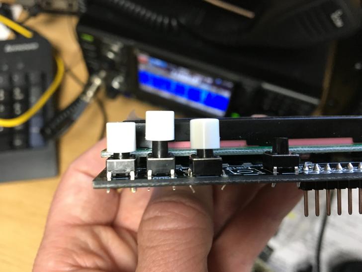
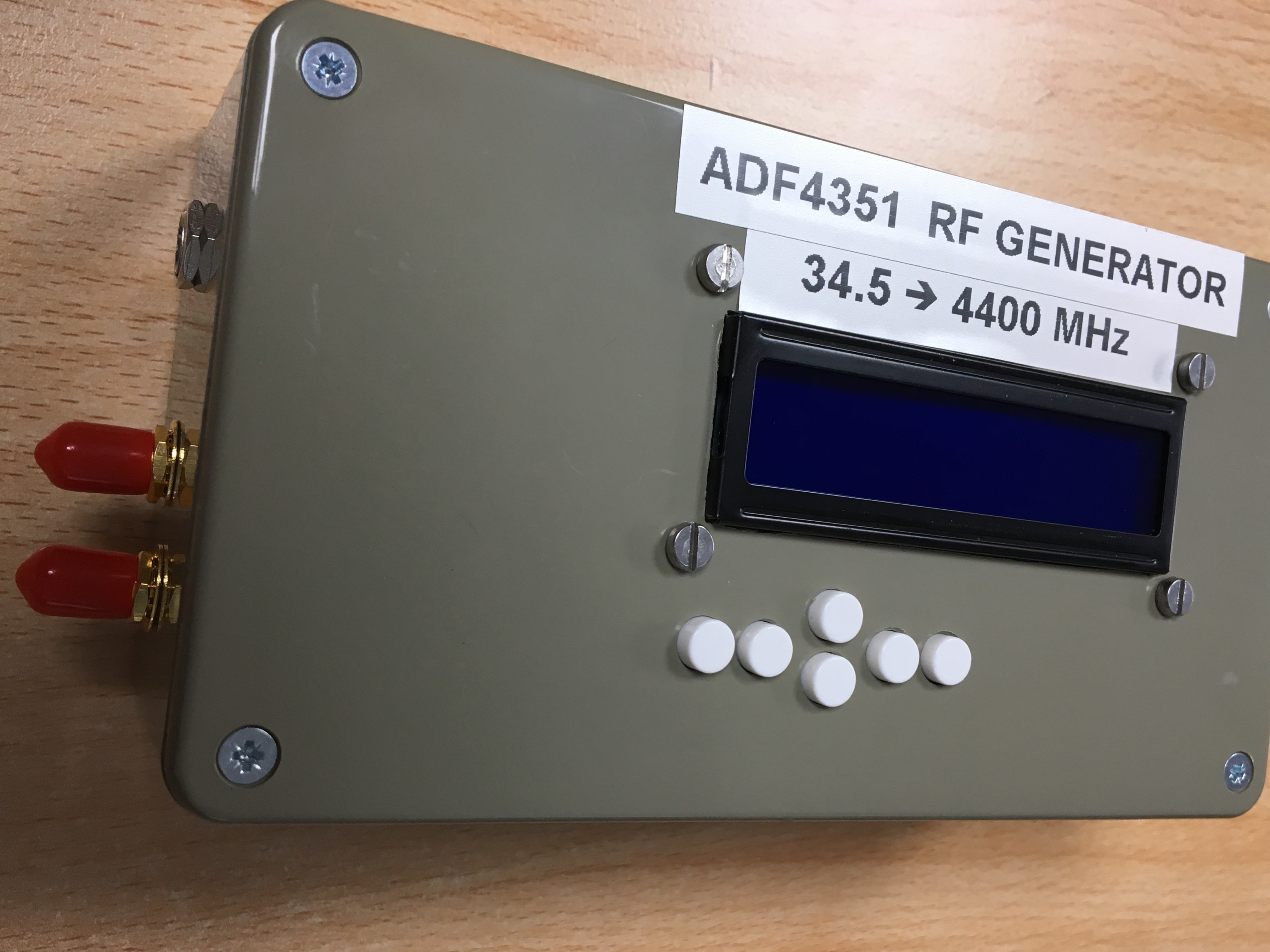
I wasn’t sure of the size of buttons to replace the originals with to allow them to be pressed when mounted in the case so I had also ordered a mixed pack on eBay to allow picking the appropriate size. I also ordered some white caps for the tops which would eventually be glued on. I eventually settled on the combination lush with the LCD.

fd7Liskg

Now came the part I wasn’t looking forward to, drilling and cutting the case. The LCD shape along with the four mounting holes was drawn out based on measurements from the board and cut. I don’t have any nice tools for the LCD rectangle cut so cut two sides with with a hand hobby saw and others with a rotary tool to compare the finish as wasn’t sure of the best approach. The rotary tool was fast but gave a terrible finish, the hobby saw plus sanding gave by far the better result.

The more tricky bit was the button measurements and I couldn’t find a PCB diagram for the board. Putting some fabric tape on the inside of the case and ink on the top of some temporary placed buttons I pushed the LCD in to it’s fitting which after a couple of goes left an imprint on the inside.

zN4jf9e

This allowed me to drill an initial hole from the inside before turning over to drill an appropriate sized hole from the other side.

7DmaZnS

Once I had validated the holes were lined up, they were expanded to fit the white caps using a drill and a deburring tool. I then checked the button lengths for the best match, soldered the buttons to the board and glued the white button caps to them.

Three holes were drilled in the side for two SMA and a DC input and some stickers added to make it look better by hiding the messy top cut made by my bad effort with the rotary tool…

W1R4LMg

The inside has the LCD shield and Arduino attached to the lid using machine screws and some spacers to hold things in place. The Arduino needed it’s DC socket removed to fit flush with the LCD shield. Wires were soldered directly in to the Arduino for the output to the resistor divider and DC input.

sDovjbOg

In the picture above the DC input is going to the Arduino DC input. However the regulator in the cheap Arduino Uno copy I’d obtained from eBay turned out not to work with a 12v input in the same way as the genuine Uno I tested with had. To sort this I skipped the regulator by putting a small buck converter in the case to let it regulate the voltage to 5v and connected it directly to the 5v on the Arduino.  As well as solving the problem, the converter gives better a 6-20v input range potentially at the expense of the converter introducing noise.

ppvdHeC

The harmonics produced are strong enough to provide an accurate marker at 10GHz and likely beyond.

Node-RED & IRC with ON4KST Chat

Background

Continuing with using Node-RED to handle messaging for radio related things I’ve created some flows for using with the interactive chat service at www.on4kst.com.

This web and Telnet based messaging service is invaluable for VHF+ users for contests, scheduling and band related chat.

The web interface is great for using while at home but when out portable using a mobile device it is a bit fiddly. Additionally, during contest/activity days, the messages can be flying by so quickly a page of text can scroll past in a moment and it’s easy to miss out messages even when directed at you with the /cq prefix. After my last outing portable I returned home to see I had been called but hadn’t noticed.

Prompted by some discussion of this on the ukmicrowaves mailing list and a mention of IRC which I use a lot I thought I should have a go at sorting something out for myself and others if interested.

There are applications that can be used to access KST chat such as the contest logging software tucnak for raw access to the telnet interface and the Windows application kst2me which runs wellin Linux with Wine. Kst2me is great and would be the likely solution for most people with a computer to hand but it’s doesn’t solve my mobile device and alerting requirements.

Using Node-RED & IRC

By pulling the ‘kst chat in to Node-RED my intention was to filter messages to channels on an IRC service based on their content:

  • A channel for all chat, effectively a mirror of whatever chat it’s connected to.
  • A channel for nearby DXCC entries. As I’ll be using this for microwave outings I have some filtering if required during busy periods.
  • A channel for direct messages sent to me with the /cq prefix so I have everything directed to me in one area.

I also want to be able to send messages to KST from my own IRC client via the channels above. A two way set-up is intended for a single user and care needs to be taken to ensure that messages sent to KST are coming from the legitimate logged in user.

I’ve used IRC here because I am comfortable with it and have clients connected to IRC servers 24/7 and can connect to these clients from any device to pick up where I left previously. This means I can leave the Node-RED flow running at home on a contest day and connect to the IRC server as I need and have a full view of everything that has happened in each of the channels. This also means I don’t have to worry about disconnections or leaving it running all the time running batteries down.

Node-RED is however  extremely flexible and allows the messages to be sent to pretty much anything such as an MQTT broker, SMS messages, DMR SMS messages, Web APIs, TCP/UDP servers etc so the use of IRC here should just be taken as an example use.

I have also set the flow up to have CQ messages directed to me on KST to send me a direct message on Twitter to gain my attention on my mobile device when not viewing the IRC channel. I could have used SMS here but the Twitter application with alerts works as well and doesn’t require using a paid for SMS service.

Interfacing With KST Chat – Login

There are two interfaces to the KST chat, the web interface and the Telnet interface, there’s no API that I’m aware of. In this instance I’ve used the Telnet interface to interact with the service as it’s the least complicated for scraping purposes.

In order to log in via Telnet we need our username, password and the band chat we wish to connect to, once these have been provided we are placed in to the selected band chat room. The Telnet outout is shown below connecting to the quiet Warch chat number 11 for test purposes.

Free text at this point will appear in the chat channel and commands need to be prefixed with a forward slash, for instance /quit.

We can log in to the Telnet interface easily with Node-RED using built in nodes and very little customization.

The flow above will initiate the connection to the ON4KST Telnet interface and log in. The nodes do the following:

  1. The first node is set to execute on start-up and contains three values, username, password and the chat number.
  2. The function node takes the user, pass and chat, splits them and sends the username to output 1, the password to output 2 and the chat room number to output 3.
  3. These three outputs are then connected to a TCP Request node, this node takes a hostname and port number, http://www.on4kst.info:23000 in this instance. This node allows both input to and output from the TCP connection.

We also have two delay nodes, as the user, password and chat are entered separately and prompted one after another, we insert a delay after the username and password to allow the next prompt to be displayed. If they are all sent at the same time the ‘kst Telnet interface will not accept them.

If we connect a debug node to the output of the TCP request node we will see the output from the telnet session.

Remember that anything sent to the interface will be immediately sent to the channel so take care not to send your password to an already connected interface. This has caught me out already!

Interfacing With KST Chat – Output

The output from the TCP request node is fed straight in to a function node with four outputs. The function node filters and alters data and directs it to the correct outputs. The four outputs link the function node to three IRC channels and one Twitter output.

The Process Output function node does a number of things. It firstly converts the utf8 input from the TCP node in to a string and strips out newline characters. This allows us to work with it easily.

It then splits the incoming messages up if they are identified as normal messages. The message format is as follows with TOCALLSIGN being the optional CQ message and the NAME being of a variable length:

TIME FROMCALLSIGN FROMNAME > (TOCALLSIGN) MESSAGETEXT

Once we have each of the above split in to variables we start to make decisions as to what to do with the incoming messages based on regex matches.

We have three IRC channels set up for this test, one for all KST chat, one for local KST chat and one for CQ messages directed at us.

If a message matches our callsign, when someone send’s a /CQ message to us, the message is sent to all of the four function outputs resulting in it appearing in all IRC channels and a message to our user on Twitter.

If a message matches a list of prefix’s local to me (2/M/G/EI) they are filtered to the local area IRC channel and also to the all KST IRC channel. This means I have filtered IRC channel containing British Isles chat, which for me in GI matches what I’m able to work, if I was in a position to work other countries it’s easy to add them to the list.

If a message is not a CQ directed to me or in the list of filtered prefixes it is placed in the all KST channel which can be monitored when traffic isn’t heavy.

Interfacing With KST Chat – Input

I have two Input types set up to send text to the KST Telnet interface.

The first was set up for testing purposes in the Node-RED interface and consists of buttons that will send commands when clicked. These buttons send the text to a function node than adds line breaks then forwards them to the TCP request node input.

The second takes input from the IRC channels I’ve configured Node-RED to connect to and carries out some validation of observed messages, processes them then forwards to the add line feed node for sending in to the TCP node.

The Process IRC node checks incoming messages and matches them with some rules. It requires that incoming messages originate from the channels the IRC node is connected to and from a username that matches my IRC clients username.

Once this incoming messages are validated, the node checks the content for commands before actin. For instance it will parse “CQ CALLSIGN Good evening”, prefix the CQ with a forward slash and send it to the telnet service  and it will appear as a valid “/CQ” command on the KSTchat.

Wrap Up

IRC is just a single communication method here, we could do this using any other messaging platform and integrate in to applications easily enough and make this more interesting easily enough. Node-RED allows easy control of messaging and simple coding in JavaScript to manipulate things.

I hope to try the described setup while portable with my microwave setup some time and imagine that the messaging ability to alert me to calls, and the use of a persistent IRC client to interact with people should allow me to keep track of KST chat in a manner I’m more comfortable with. (I did try this in a contest weekend up a hill and it worked just fine!)

My code is a horrible mess but I can forward it to anyone that would like to try something like this out. Here’s the whole thing:

Please have a look at some other Node-RED posts for more amateur radio uses if interested in the above:


A Node-RED Module for DMR SMS using an openSPOT

I’ve been using Node-RED to send DMR SMS alerts for about 6 months now as described in the earlier post here. This has worked perfectly until now but I would rather have a single configurable node instead of a collection of nodes containing code, so here it is.

Once installed, the node will be available in the social section and can just be dragged in to the flow. The image below shows the previous setup at the top where a number of different nodes were used and the new setup with just the one node and an input.

Once the node is in the flow, the openSPOT server will need to be configured within it by selecting the edit icon next to the openSPOT drop down. The defaults in the server section should suit a basic default install on a local network.

Each SMS node can be configured with all of useful options as described in the HTTP API documentation. The main requirement is that a destination ID is entered, this will be your DMR ID if you’re using this for sending messages to yourself. The rest of the configuration options are as described in the API documentation.

Once configured, any string payload sent to this node should send it to the radio.

The module is available at https://www.npmjs.com/package/node-red-contrib-openspotsms and can be installed in an existing Node-RED instance by changing in to the instance directory and running:

npm install node-red-contrib-openspotsms

It’s also available on github if you’d rather grab it manually. I’m no coder so it’s very messy but it seems to work for now, I’ll get through the todo list in time!

Christmas With RfCat

Having lost the RF remote controlling the power to the Christmas tree lights a couple of times I thought it would be a good time to try RfCat with the YARD stick one that has been sitting neglected since I bought it a while back. Nothing here that hasn’t been written up 101 times by others!

The RF controller has multiple buttons for switching the different mains switches on and off individually or all on/off at the same time. As these are only button presses I’ve just aimed to replay the transmissions not really caring about the content.

The signals are on off keyed and repeated when holding the button, looking at these in audacity was pretty much as described in earlier posts here and here. It’s been a while since I’ve done this sort of thing so was a decent refresher project.

Additionally this time around I’ve used inspectrum with the IQ output from GQRX which along with its cursor option makes getting the timings correct a lot easier.

screenshot-inspectrum-gqrx_20161209_103307_434173979_1800000_fc-raw

Inspectrum with cursors enabled

Using the stats.py script as described in earlier posts with a wav file to make a guess gave the following output (not from the same button as in the screenshot):

./stats.py -i ../allon.wav -c 1 -t 30
 The whole lot: 000000010101111110000001001001010101001010001010010101010010101010100100100101001010010100100100101001000100101001010100101001

After removing the initial zeros this matched up nearly perfectly with the inspectrum/audacity output. I added an additional 1 and 0 to the long on/off periods at the start to have it match better.

Now I needed to send this out using the RfCat with the above input. This was surprisingly easy to get working in Python with RfCat and worked the first time after following some online examples.

Firstly I needed to convert the stream to use with RfCat which gave:

\xaf\xe0\x22\x2a\x8a\x28\xaa\x2a\xa2\x22\x8a\x28\x88\xa2\x22\xaa\x22\x20

Then to send this in RfCat:

d.setMdmModulation(MOD_ASK_OOK)
d.setFreq(434400000)
d.setMaxPower()
d.setMdmSyncMode(0)
d.setMdmDRate((int)(1.0/0.000450))
d.RFxmit("\xaf\xe0\x22\x2a\x8a\x28\xaa\x2a\xa2\x22\x8a\x28\x88\xa2\x22\xaa\x22\x20")

The timing was taken from the inspectrum symbol period as pictured above, modulation and frequency self explanatory.

Comparing the original signal to the one sent by rfcat they are pretty much the same and the switches accept the signals as intended.

screenshot-59

Original signal top, RfCat bottom

I wrapped this all up in a small python script containing all the on/off values and am now using it to turn the lights on and off with a cron job for the month.

Another way to receive the data and skip the iq/wav analysis full stop is just to use RfCat to receive the signal.

I did try this first and didn’t get too far before trying the above instead but it was easier after having done all of the above and having the timings correct and after reading a great post here which is a good guide to this sort of thing: http://andrewmohawk.com/2015/08/31/hacking-fixed-key-remotes-with-only-rfcat/

With the same RfCat settings as above we run d.RFlisten() and get the following:

screenshot-60

RfCat button press output

There’s some obvious repeated data in the screen shot. Taking a few of the repeats out and converting to binary we end up with a string that matches the output from stats.py but for a slightly longer preamble but this doesn’t make a difference to the outcome when we retransmit the above, the switch switches as expected.

It is a lot quicker and less fiddly to just do all of the above with RfCat entirely but had I not worked through it from the method I knew already I’d have struggled to get it working as quickly. Next time with a little better understanding hopefully it will be easier.

WSJT-X alerts to MD-380 with the openSPOT HTTP API

DMR SMS alerts using the SharkRF openSPOT with Node-RED

I recently acquired a SharkRF openSPOT for use as a hotspot to connect to the Brandmeister DMR network with my MD-380 DMR radio as I have no easily accessible repeaters nearby to use for DMR.

I have nothing but good things to say about this device, it works very well, the UI is simple to use, reported bugs are fixed very quickly and new features added with new firmware. The icing on the cake is it is a very accessible device with a HTTP and UDP API to interact with! I’ve only toyed with some features in the HTTP API but happy with what I’ve seen so far.

The first use I came up with for it was receiving DMR SMS messages to my MD-380 from my existing WSJT-X & Node-RED setup. The status-dmrsms API allows us to receive and send SMS messages over the local RF link to our connected DMR radio by specifying its DMR ID. This functionality works exactly as described in the API documentation now and if you follow it you will get a beer.

BEER

BEER from the SharkRF openSPOT HTTP API

In order to get this working in to Node-RED a flow was needed to handle authentication. As described in the Login Process, we need to hash our openSPOT password with a provided token to get a digest for use in all communication to the API, this digest is valid for 60 minutes.

The flow below shows the authentication process it as set up at the moment.

Node-RED openSPOT API Login

Node-RED openSPOT API Login

The inject at the beginning just sends a time stamp, which is unused, to start this flow off on Node-RED start-up and every 30 minutes thereafter. After the login is posted some global variables are set with the login status, the token and the digest if authentication was successful. This should hopefully tick away to ensure we will have a valid digest to hand at all times.

The posting of messages is easy and exactly as documented in the API description. With the digest already in a global variable from the login process above, we take any text input, limit it to 75 characters, convert to UTF16BE HEX and post it in the correct format for our radio. The full flow including the message input from WSJT-X is pictured below.

Full flow for using the openSPOT API

Full flow for using the openSPOT API

The inject function in the send flow is just there for testing purposes to insert a test message manually and the success function at the end just writes the status to the debug console.

With the above all set up we just wait for the DX to light up our DMR radio with an SMS message, the image below shows this on an earlier version of the same flow.

WSJT-X alerts to MD-380 with the openSPOT HTTP API

WSJT-X alerts to MD-380 with the openSPOT HTTP API

Alerts from Node-RED via Twitter or IRC might be easier but at least with the above it is all contained on the RF side and doesn’t need the Internet 🙂

It has been running for a few days now and seems to be working fine. I’ll try and wrap it all up in a more easily deployed function if I get the time but if anyone wants the nasty code before then just drop me a line.

Node-Red WSJTX

WSJT-X monitoring with py_wsjtx & Node-RED

An article about Node-RED by G4WNC in a recent Practical Wireless gave me the push to try and use it in my own radio set-up for alerting and monitoring using a spare Raspberry Pi.

The goal is to receive notifications when my own local radio spots new DXCC on HF bands, any WSPR or JT spots on 6m+ and to plot the 2m JT65b beacons I can hear over time amongst other things.

Prior to this I was only monitoring the beacons using a script and forwarding this to openHAB over MQTT to display alongside some house statistics. This wasn’t too flexible and openHAB is a bit of a burden on the Pi which would randomly hang.

For this project I’m wanting to take inputs from different physical radios & SDR with multiple copies of WSJT-X to display, log certain decodes and alert me in multiple ways if interesting things are seen.

The set-up currently has three radio inputs, each of these has a WSJT-X instance with its own configuration:

  1. HF Radio (IC-7300 and/or FT-817)
  2. VHF Radio (FT-847)
  3. GQRX (IF out of FT-847)

Input 1 is set to whatever I’ve left the HF radios monitoring.

Inputs 2 and 3 are usually set to monitor the two JT65B enabled 2m beacons I can hear from this location, GB3VHF and GB3NGI, using the same antenna. I have this graphed on openHAB but it’s not working great so will be using something else and graphing from the database instead at some point.

WSJT-X can output status messages and decodes over the network to a configured address, this is discussed in a previous blog post where we split the output to AlarmeJT and CQRLOG. We will add a third listener on an extra port, py_wsjtx.

Py_wsjtx is a Python network listener that takes the network output from WSJT-X and displays it in a console, either line by line or a curses interface. I have all of the WSJT-X instances sending their data to a single py_wsjtx instance.

py_wsjtx

As can be seen above, this is really handy for monitoring things from a console rather than the GUI and will highlight new DXCC spots and CQ calls. It can also output the decoded messages to an MQTT broker if configure which comes in really useful for what we’re doing here.

Node-RED allows us to easily take these MQTT inputs, process them in whatever way we want and act upon them. The image below shows the current set-up.

Node-Red WSJTX

The purple boxes are MQTT inputs and outputs, each of these points to an MQTT broker (running on the same Raspberry Pi) and listens or sends messages for a particular topic. Py_wsjtx sends MQTT messages in the format py_wsjtx/WSJT-X radioname/messagetype which makes it easy for us to configure Node-RED to process them in the correct manner for instance filtering by radio or by decode type.

Working from the top row of the flow down:

  1. GQRX and FT847 JT65b beacon decodes are converted to JSON, then they are forwarded on in three ways:
    1. All decodes go to openHAB which is graphing things at the moment, this is shown in the image below and I have it copied to my qrz.com page, I’ll be changing this shortly to something more reliable/configurable.Beacon monitoring
    2. All decodes are logged to a MySQL database which I will use for generating graphs when we stop using openHAB.
    3. If the decodes are above set levels, <5 for GB3NGI and <20 for GB3VHF, then send a post to twitter and to me on a local IRC server.
  2. Next we have DXCC alerts from WSJT-X, if it spots a new country then a message is sent to twitter and IRC with the spot, hopefully I will see it and respond. To make it more interesting I had it ring the shack doorbell, I’ve got two ways to do this, using a HackRF to replay the wireless doorbell, which is a bit of a waste of an expensive SDR, or ringing via a second remote unit using the Pi GPIO pins. The ringer got annoying quickly so it’s now turned off, flashing a light may be better!
  3. Next up we have an input for any WSPR spots on any radio. I’m not doing much with this at the moment other than alerting me on local IRC/twitter if there are any spots on 6m/4m/2m, I don’t often have WSPR listeners on these band though but if I think conditions are looking likely I will switch one of the WSJT-X instances to it.
  4. The solar inverter statistics are sent out on 433.9mhz and I use an RTL SDR dongle to receive them and decode with the program rtl_433. These are then rate limited and forwarded to openHAB as well as being written to the database.
  5. The other MQTT inputs are DHT11 temperature and humidity sensors in the house hooked up to various Pi I have. I’ve not got around to doing anything with these in Node-RED yet but they are currently used by openHAB.

Not much more to say other than it works well for me and I plan on playing about with the flow some more to add some more alerting rules and cutting openHAB out of the solution entirely by graphing the outputs from the database in a more accessible way.

Solar PV Output in openHAB Using RTL_433

I’ve been playing a little with the fantastic open source home monitoring and automation solution openHAB on a Raspberry PI 2 . Having started off with some small temperature/humidity sensors I was looking for something else to add and the stats from the Solar panels were an obvious want.

I previously had the Inverter monitored using using Auroramon as described here. This was great but it’s stopped working and I’m putting off crawling around the attic to debug the issue for as long as possible.

I can keep an eye on the Inverter output using a standalone wireless monitor, the OWL Micro+, which has a small transmitter sensor clamped to the output from the Inverter giving current generation statistics. There is however no way of hooking this up to a computer to record the stats, so enter rtl_433..

The rtl_433 application uses an RTL SDR dongle to receive and decode a huge selection of wireless sensors transmitting on 433 MHz. I didn’t see the OWL device in the list but on running rtl_433 we see statistics generated every 15 seconds when power is being generated and totals every 60 seconds when there’s no generation.

Energy Sensor CM180 Id 62a0 power: 48W, total: 11242215648W, Total Energy: 3122.837kWh

With the output from this we can pull out the power generated and send it via an MQTT message using mosquitto_pub to a listening MQTT broker we have openHAB set up to use already.

This is ghastly but it works for now, for some reason the unit reads 48w when idle so there’s a bit of fiddling to make it idle at 1:

rtl_433 2> /dev/null | xargs -I {} sh -c “mosquitto_pub -h 192.168.1.1 -t solar -m \$(echo {} |  sed -e ‘s/, .*//’ -e ‘s/^.*: \([0-9]\+\).*/\1/’|while read spo; do if [ \$spo -gt 50 ]; then echo \$spo; else echo 1; fi; done)”

I’ve made some changes to my set-up where everything is now being fed in to node-red which processes MQTT messages so the following is a bit more simple and outputs in JSON and lets node-red do the filtering:

rtl_433 -R 12 -F json 2> /dev/null | parallel –tty -k mosquitto_pub -h 192.168.1.1 -t solarout -m {}

At the openHAB side I’ve an item “solar” set up and can see the current generation and day/week charts, it’s been running a few days now and been no problem at all!

Screenshot-16

Future plans with this one will be to capture the output in a less Frankenstein manner or maybe risk broken ribs by crawling around the roof space to fix the monitor on the Inverter.

AlarmeJT

Using WSJT-X in Linux with CQRLOG and AlarmeJT

WSJT-X offers a handy UDP network service for two way communication with other applications such as logging or monitoring software, but I had some difficulties using it with multiple applications at the same time.

WJST-X is set up to communicate with a listening UDP server in the Settings->Reporting section as the image below, by default it is set up to send packets to the localhost port 2237.

WSJT-X UDP Server Settings

There are a number of software packages in Linux that support this communication from WSJT-X such as CQRLOG and AlarmeJT.

CQRLOG uses it in remote mode to allow automatic logging of QSOs from WSJT-X saving a lot of time and errors.

AlarmeJT, pictured below, is a handy application that takes decodes and displays them alongside information such as whether the DXCC/Locator is required based on logs provided to it and can communicate in response to WSJT-X to tune to the selected call.

AlarmeJT

The only problem is by default, as far as I understand, we can only use one of these programs at a time with WSJT-X. WSJT-X sends its UDP traffic to one address/port but each of the two consuming applications will try to exclusively bind this port preventing the other application from doing the same.

WSJT-X can be configured to send to multicast addresses to allow multiple applications on the network to consume the same data. However I’m running both applications on the same workstation and one of the applications doesn’t allow the listener IP to be set and the other wouldn’t let me change the settings at all in addition to the binding issues. So the plan was to find some way of duplicating the UDP packets to multiple destinations.

Some Startpage searching before attempting to do this with iptables or Python (a quick test indicated it would be possible) identified an already written user-space tool, samplicator, that does the forwarding we need here. It is easy to compile and use.

The idea is to have WSJT-X configured to send to the samplicator listener on local port 2000 and have it send copies of the received packets to a CQRLOG listener on port 2238 and also to an AlarmeJT listener on the default port 2237.

Packet Flow
The command to implement this is as below and I’ve put it in my /etc/rc.local to run at boot.

samplicate -S -p 2000 127.0.0.1/2237 127.0.0.1/2238

Here we are listening on port 2000 and forwarding copies of the UDP packets to 127.0.0.1 port 2237 and 2238. The -S options is especially handy as it spoofs the source addresses to appear exactly as sent which allows the consuming applications to communicate in response such as to allow tuning to a station when clicking on a CQ in AlarmeJT, without this set they can just consume the data.

It seems to work well with the limited traffic we’re using here and lets me parse decodes quickly for their statistics, tune quickly to calls and to log the successful QSO automatically. Now I just need to make a few hundred contacts to make up for the time spent fiddling about with this stuff to save time…